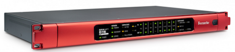
Focusrite RedNet D16 AES
- AES/EBU inputs and outputs via 2x25-way female D-sub, each wired to AES59 (combined I/O)/Tascam Digital
- Switchable AES/EBU input via XLR F connector (replaces channels 1–2 from DB25)
- Switchable S/PDIF input via phono connector (replaces channels 3–4 from DB25)
- Duplicate AES/EBU output via XLR M connector (duplicates channels 1–2)
- Duplicate S/PDIF output via phono connector (replaces any adjacent odd/even pair)
- DARS input via XLR F (switchable between AES/EBU input and DARS)
- Word clock input on BNC port (switchable termination)
- Word clock output on BNC port
- Two Dante network ports, configurable as redundant connections or for daisy chaining
- IEC power inlet
Inputs
- AES/EBU: 16 channels, with switchable SRC by input pair
- AES/EBU Connectors:
- Channels 1–16: 2x 25-way female D-Sub, each wired to AES59 (combined I/O)/Tascam Digital
- Channels 1–2 (switchable): XLR3F*
- S/PDIF Input: Channels 3–4 (switchable)
- S/PDIF connector: RCA Phono socket
- Input format: Channel status ignored. Assumed to be 24 bit, 2-channel audio
Input Sample Rate Converters
- Input sample rate range: 32 to 216 kHz
- Gain error: '-0.3 dB
- Dynamic Range: > 138 dB (-60 dBFS method)
- THD+N: < -130 dB (0.00003%); 0 dBFS input
Outputs
- AES/EBU: 16 channels, synchronous with unit sample rate
- AES/EBU connectors: Channels 1–16: 2x 25-way female D-Sub, each wired to AES59 (combined I/O) (See "Inputs")
- Channels 1–2: XLR3M*:
- S/PDIF output:
- 2 channels, synchronous with unit sample rate
- Output can duplicate any adjacent odd/even pair of channels 1–16
- S/PDIF connector: RCA Phono socket
- Output format: AES3
Digital Performance
- Supported sample rates
- 44.1
- 48
- 88.2
- 96
- 176.4
- 192 kHz (-4% / -0.1% / +0.1% / +4.167%) at 24 bit
- Clock sources: Internal or from network master device
- Local clock sources
- Internal
- DARS
- Word Clock
- Input 1–2
- Input 9–10
- External word clock range: Nominal sample rate ±7.5%
- Power Indicator: Green LED
- Primary network: Green LED, indicates that a network connection is present on primary port when in redundant mode. When in switched mode, a valid network connection at either Primary or Secondary network port will cause this LED to illuminate
- Secondary network: As Primary network indicator. Not used in switched mode.
- Locked: Green LED. When unit is network slave, shows valid network lock, when network master shows unit is locked to indicated clock source. Flashing means invalid external clock present and unit has reverted to internal clock
- Unit sample rate: Orange LED for each: 44.1 kHz, 48 kHz, x2, x4
- Pull up/down: Indicates unit is set to operate on a Dante pull up/down domain
- Signal indicators: 16 Green LEDs, 8 input/8 output indicators. Illuminate at -126 dBFS
- Clock source indicators: Orange LED for each: Internal, Word Clock, DARS, Input 1–2, Input 9–10
Network Modes
- Redundant: Allows unit to connect to two independent networks
- Switched: Connects both ports to integrated network switch allowing daisy-chaining of devices
- PSU: Internal, 100-240V, consumption 30 VA
| Locatie | Zaandam |
| Verhuurder | P&P Performance |
| Afstand | |
| Aantal beschikbaar | 3 stuk(s) |
| Prijs p/d | € 25,00 |
| In winkelwagen |